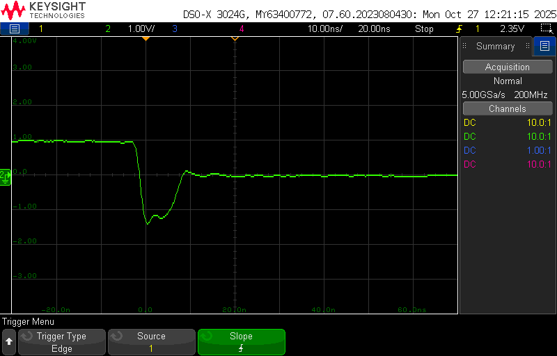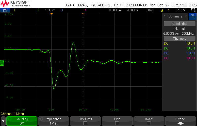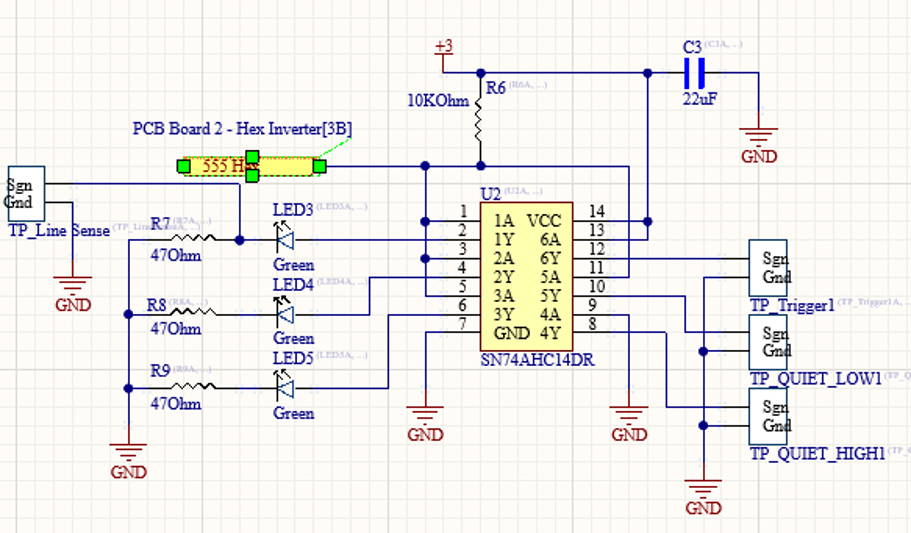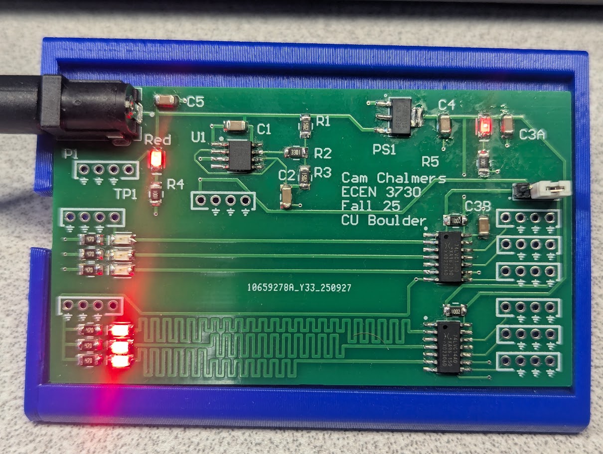
For this project, I designed a PCB to demonstrate how sharp di/dt transitions and poor routing practices can cause noise on other lines. This PCB has two victim lines, each with its own set of aggressor lines. One victim line runs over a continuous ground plane and terminates into it immediately. The aggressor lines run cleanly and parallel to the victim line. The other victim line has no ground plane. The return path is a single trace that runs all the way back to the start of the victim line.
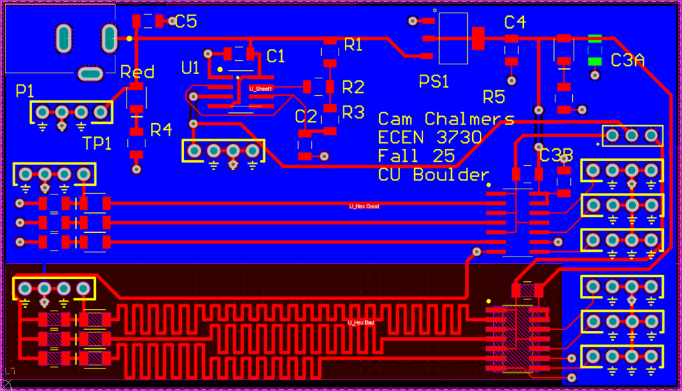
Additionally, for the Bad Circuit, I designed the traces to have different lengths and an inconsistent effect on the return trace. The Different lengths would spread out the effect, disrupting the natural ringing down. The Zig-Zag nature of the signal traces would create a series of micro-pulses on the return trace instead of a single big pulse.
The magnetic field created by current flow moves out radially, not longitudinally. When that magnetic field crosses a conductor, it induces current flow along that conductor. When current flows in a trace toward the return trace, no inductive current is generated in the return trace. However, when the signal trace turns and runs parallel to the return trace, the current pulse will create an inductive current in the return trace. This causes the Zig-Zag pattern to create a series of inductive current pulses, instead of a single pulse.